Author: Brian Ivie
Email: [email protected]
This file: https://bit.ly/beginning-electronics
This tutorial is an introduction to using basic electronic components such as resistors, LEDs, wires, a Breadboard, and others to create simple electronic circuits.
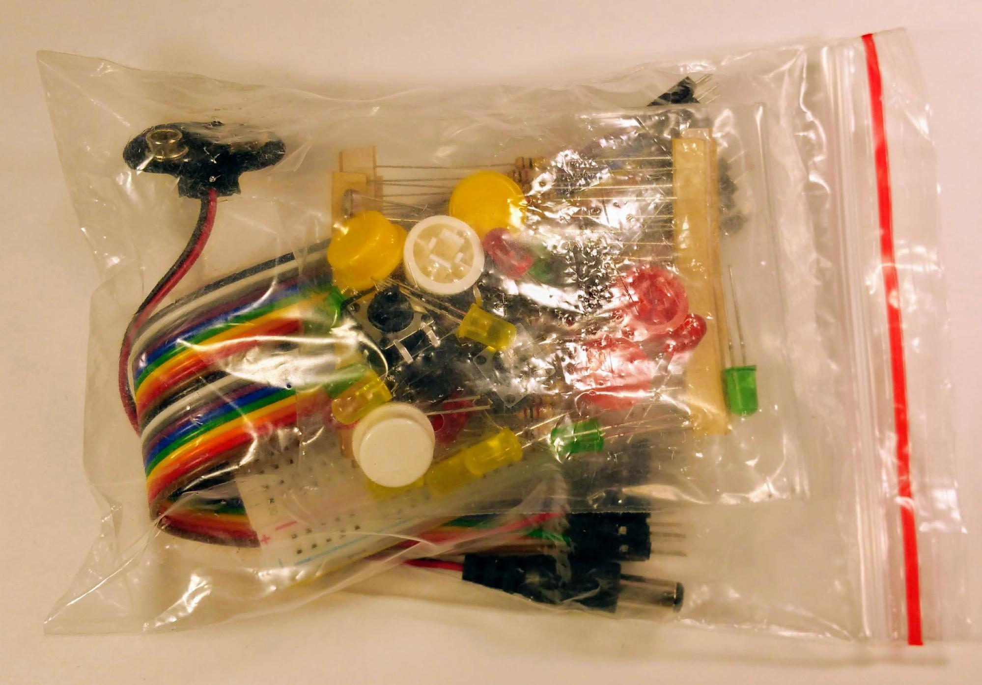
We will be using the breadboard and wires from the “parts bag”. For our first circuit we will also use a resistor and LED so that we can tell when we’ve hooked up power and everything else correctly. Once you have the parts you need, please put the rest of the parts back in the bag to keep them from getting lost.
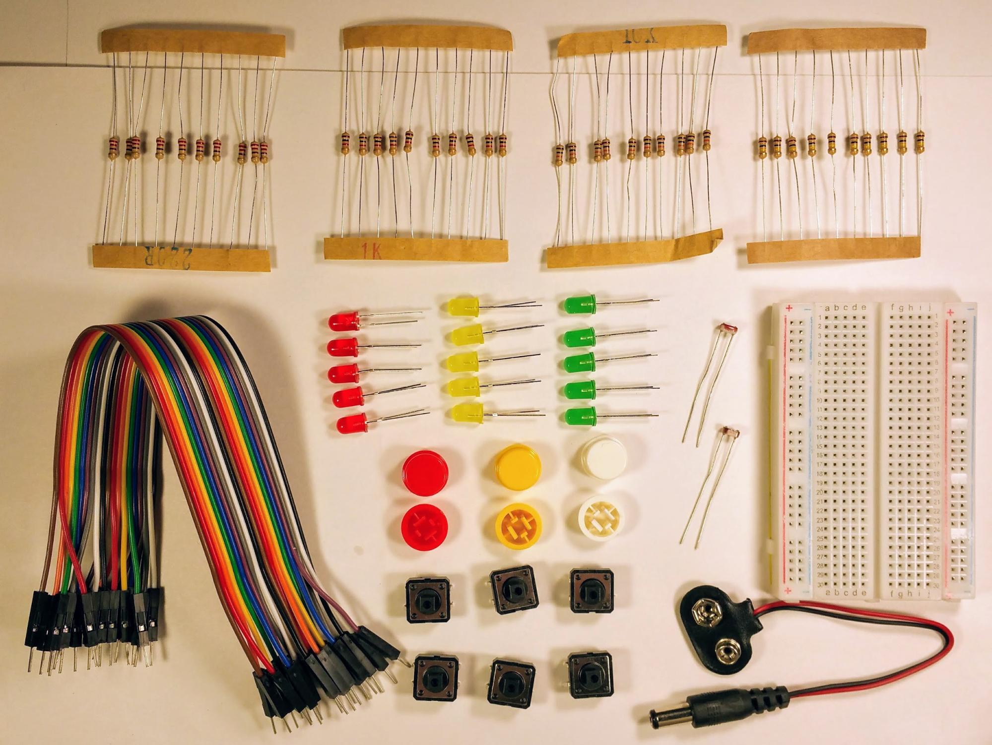
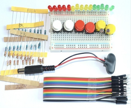
Here are all of the parts of the parts bag layed out. Notice there are four sets of resistors (there are ten of each of 4 different values of resistor). There are 15 LEDs, with three different colors. There are 6 buttons, and 6 button caps. There are twenty colored wires. When the kit is new these wires will be in one strip, we will be pulling these apart so that we can use them separately. There are two CdS photocells, a breadboard, and a 9V power adapter.
Resistors limit how much current passes through a circuit so that electrical components don’t have too much electricity flow through them, get hot, and burn out.
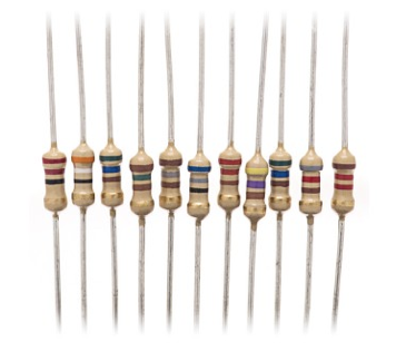
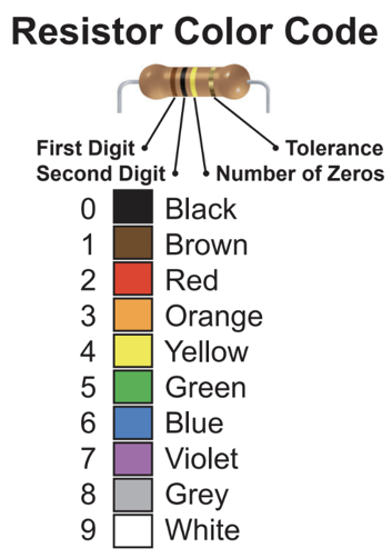
The value of a resistor is determined by three of the color bands on it. The fourth band, which in our case is always gold, determines the tolerance of the resistor (how much it varies from its stated value). The first two bands are the first two digits of the value. The third band is the number of zeros. Three zeros (000) are replaced with a ‘K’ and 6 zeros (000,000) are replaced with a ‘M’.
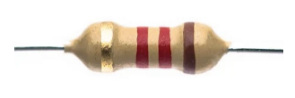
What is the value of this resistor?
Notice how the gold band is on the left… (I’m tricky like that). To determine the value of this resistor, you would first flip it so the gold band is on the right:
Then you would read the colors: Green-Blue-Black. This would be 5-6-0 so 56 + 0 zeros or 56 ohms.
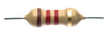
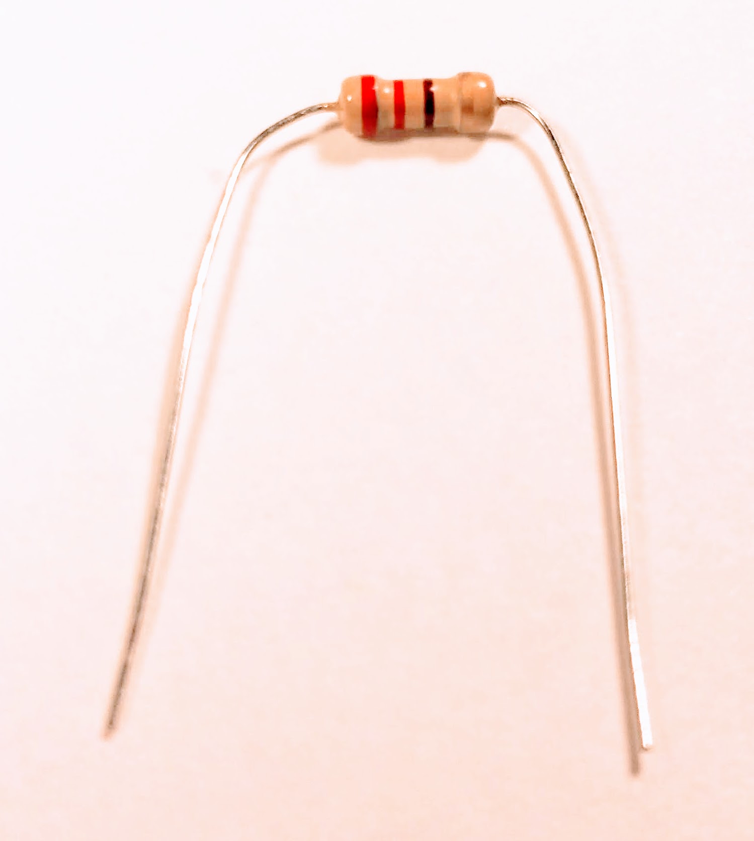
What is the value of this resistor?
(Don’t forget to flip it)
Brown - Red - Red = 1 - 2 - 2 = 1 2 + 2 zeros = 1200 or 1.2 K
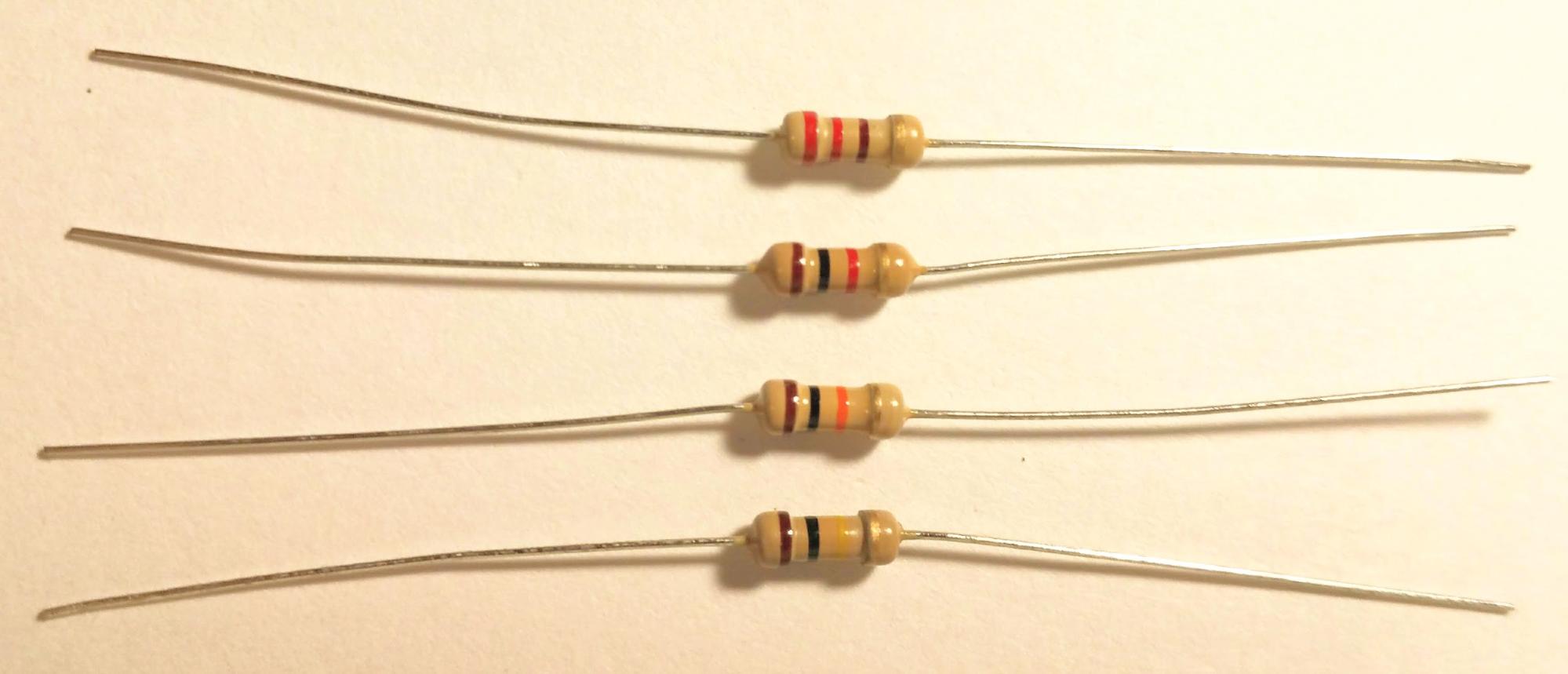
There are four different values of resistors in our kit. They are 220 ohms (Red-Red-Brown), 1K (Brown-Black-Red), 10K (Brown-Black-Orange), and 100K (Brown-Black-Yellow).
Breadboards
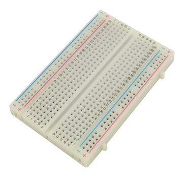
We will be using a breadboard in order to connect the various parts of our circuit together:
A breadboard has metal tabs on the inside back. These connect together any parts that are in one of the two middle columns that are in the same row. There are two long columns on each side. These are typically connected to power (the +) and ground (the -), and these two columns on each side are often referred to as the “power rail” and the “ground rail.” Please note that the two rails on one side aren’t connected to the two rails on the other side. (If you want them to be connected, you need to run a wire from one side to the other for each rail.)
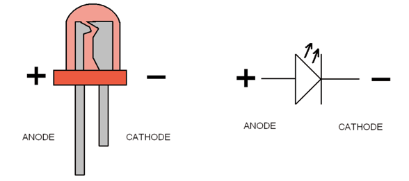
A LED (Light Emitting Diode) is an electrical component that lights up when current travels through it. The amount of current needs to be limited so that it is less than 20 mA (milli-amps) or the LED might burn out. Photons are emitted when the electrons traveling from an outer shell of one atom, fall to a lower level of a different atom. A LED is “polar” which means it only can be connected one way in a circuit or it won’t light up. The longer lead is the positive side and the shorter lead is the negative side.
Inside an LED you can see that the positive side is small, like a pole, and the negative side is larger, like a flag. The schematic symbol for an LED shows this polarity with a triangle pointing from the positive side to the negative side (this was before they figured out that electrons were negatively charged as defined by Benjamin Franklin).
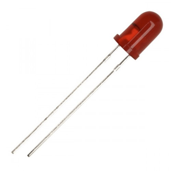
Can you tell which lead of this LED is positive and which one is negative?
The upper lead is positive (it is longer) and the lower lead is negative (it is shorter).
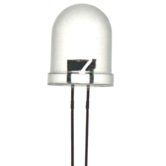
Can you tell which is the positive and negative lead for this LED?
(The two leads have been trimmed, so they are the same length). If you look inside, you can see that the “flag” part which is negative is on the left, and the smaller “pole” part which is positive is on the right.
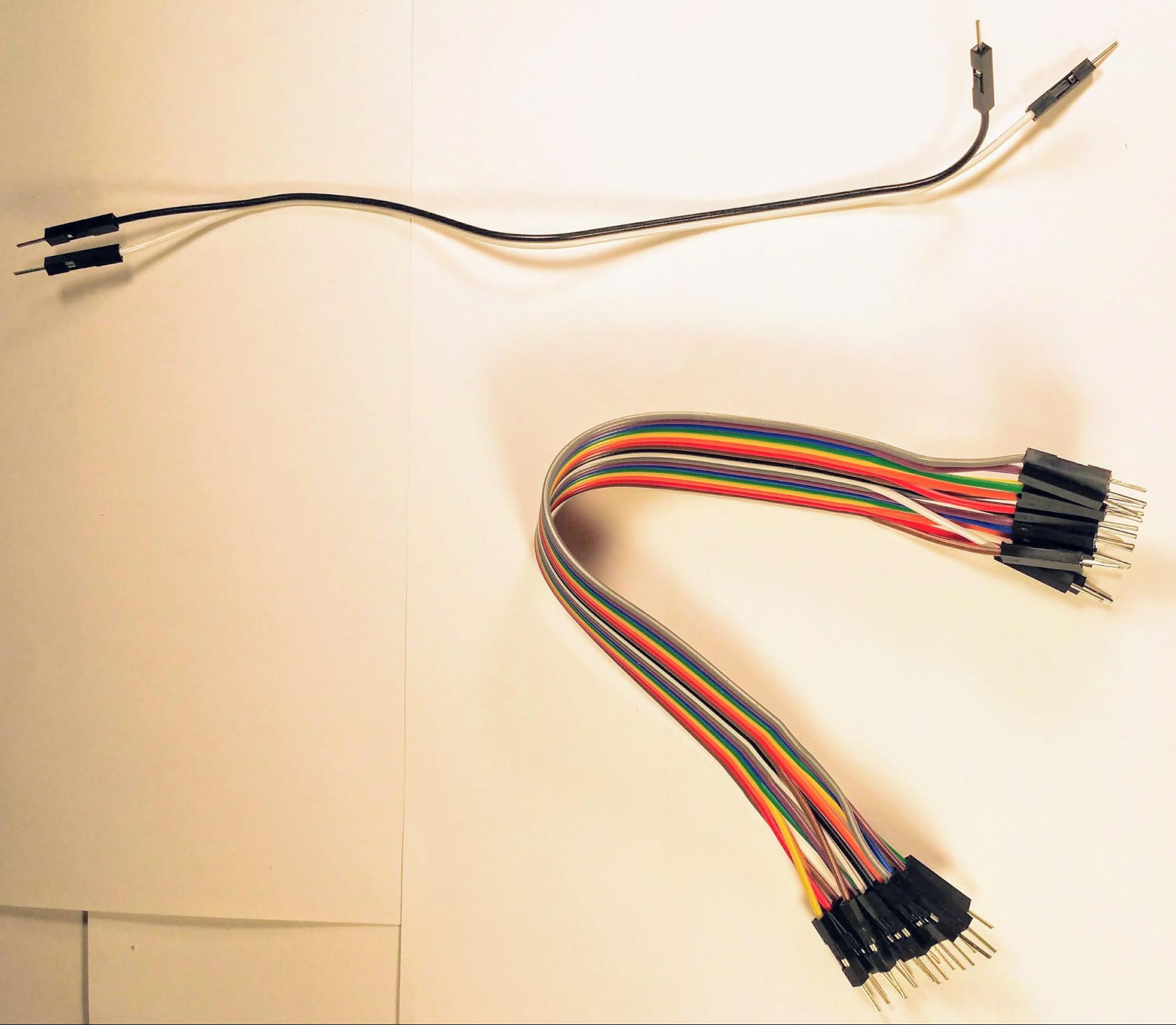
Separate off two of the wires from the strip of wires (if they are still connected together). These will be for connecting power (5 volts) and ground to the breadboard.
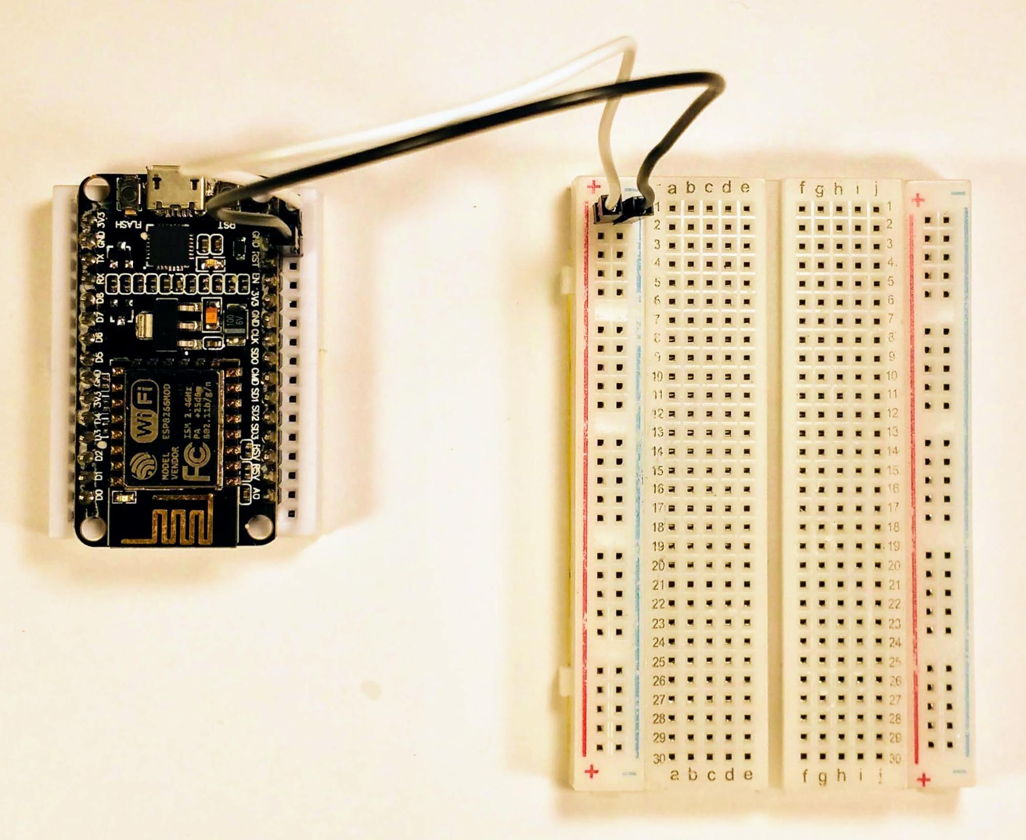
Connect the Vin pin (5 volts) of the NodeMCU module to one of the pins on the breadboard that is next to the red line. We’ll call all of the pins on this side of the breadboard that are next to the red line the “power rail.” It doesn’t matter which of the holes the wire is plugged into as long as they are next to the red line.
Run a second wire from one of the ground connections (I used the one that was right next to “Vin”) to one of the holes next to the blue line on the left side of the breadboard. This column of holes will be “ground” for our circuit.
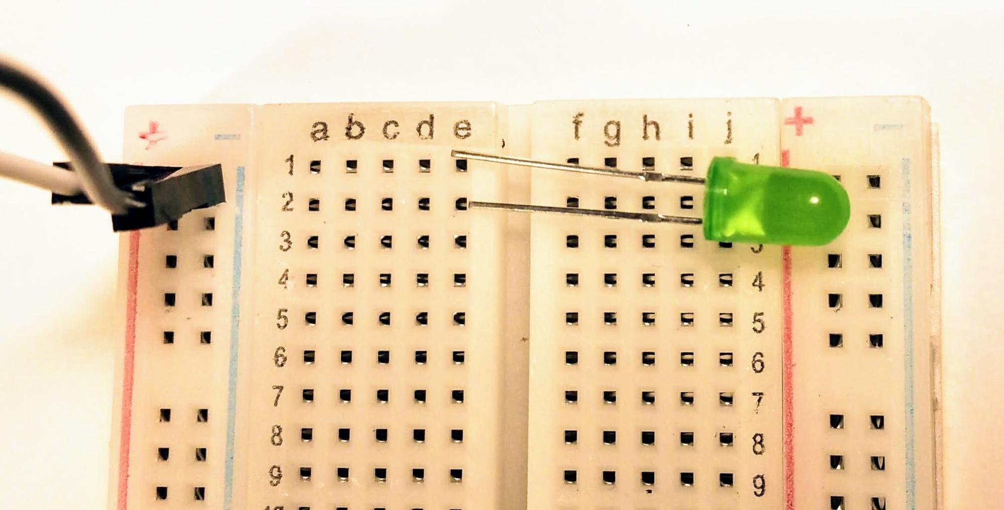
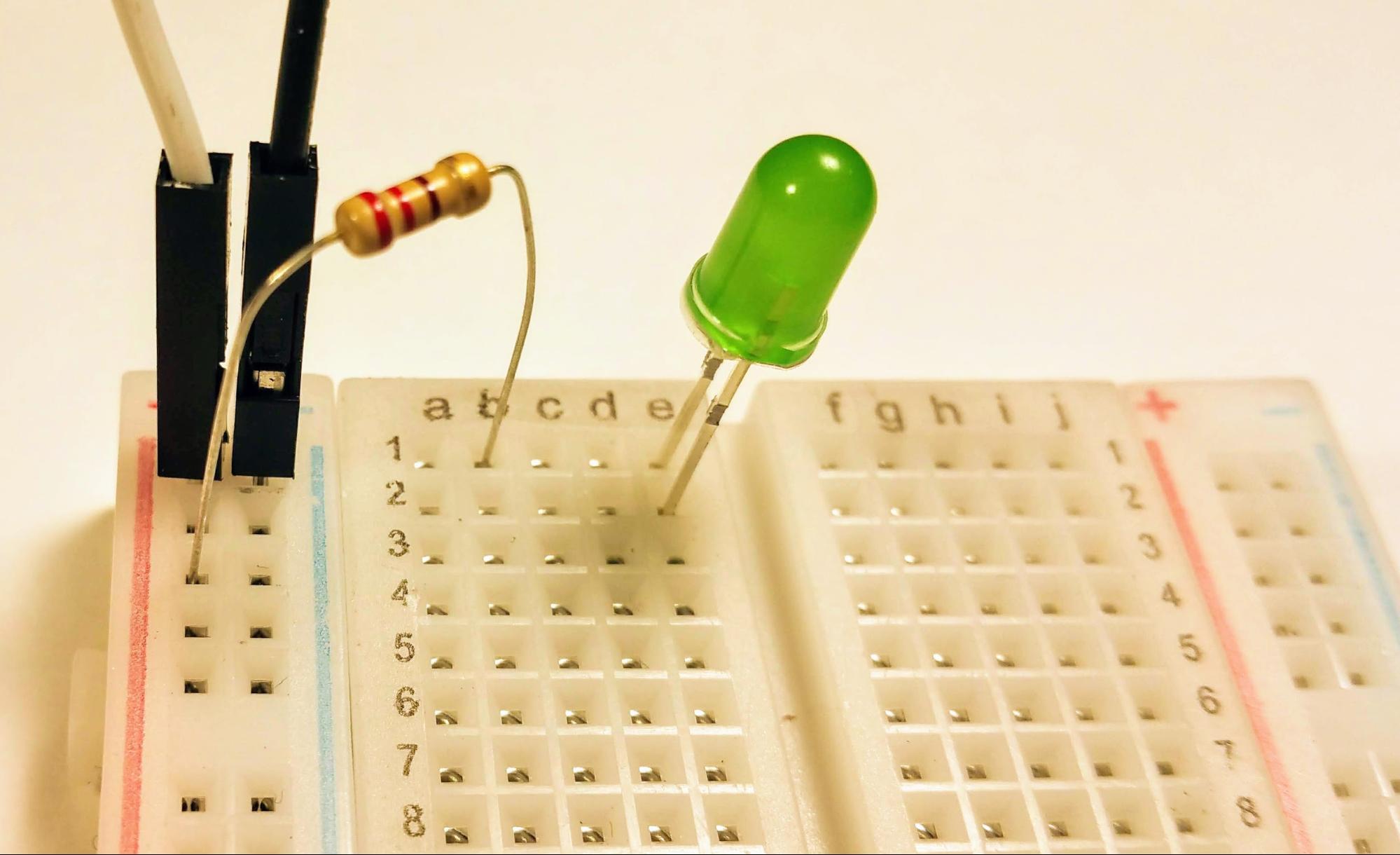
Choose an LED (I picked a green one, but the color doesn’t matter). Plug it into the breadboard on two different rows. I placed it in column ‘e’ so it would be near the middle. Place the positive side (longer lead) into row one (e1) and the negative side into row 2 (e2) of the breadboard.
Press the LED down into the breadboard at a 90 degree angle so that it connects to the connectors that are inside the breadboard. Now anything that is plugged into one of the holes of the left-sided row 1: a1, b2, c1 and d1, will be connected to the positive lead of the LED. Anything that is connected to the left-sided row two: a2, b2, c2, and d2, will be connected to the negative lead of the LED. I say “left-sided” because the right-side of the breadboard’s row 1 or row 2 isn’t connected to the left. So f1, g1, h1, i1, and j1 are connected together, but they aren’t connected to a through e of row 1. The same goes for f2, g2, h2, and i2, they aren’t connected to a2, b2, c2, d2, and e2.
Remember the four different values of resistors that we have. We need a resistor to limit how much current flows through our LED. After we do a little math with Ohm’s law, V = I x R or 5 Volts = Current x Resistance or Resistance = Volts / Current or 5V / 20mA, we find out that we can use either of the two lowest values of resistors. We could use the higher valued resistors, but our LED would be so dim it would be hard to see.
I chose to use a 220 ohm resistor (Red - Red - Brown) so that my LED would be bright. Bend the leads of the LED so that they can be slid easily into the breadboard. If we were doing this professionally, we would cut these shorter so the LED didn’t stand up so long on the breadboard, but since we’re going to be using these resistors in lots of different projects, let’s leave the leads long.
By placing the resistor so that one side is connected to one of the holes next to the red “power” rail, and the other is in the row the positive lead of the LED is in, we effectively connect +5 volts power through a resistor to the positive lead of the LED. It doesn’t matter which of the holes next to the red line that we use, nor which of the holes (a1, b1, c1 or d1), just as long as one side is connected to power, and the other to the lead of the LED.
Now that the positive pin of the LED is connected through a resistor to power, we’re ready to connect the other pin of the LED (the cathode or negative) pin of the LED to ground. We do this by plugging in a wire to one of the holes a2, b2, c2, or d2, and the other side of the wire into one of the holes next to the blue line or ground rail on the left side.
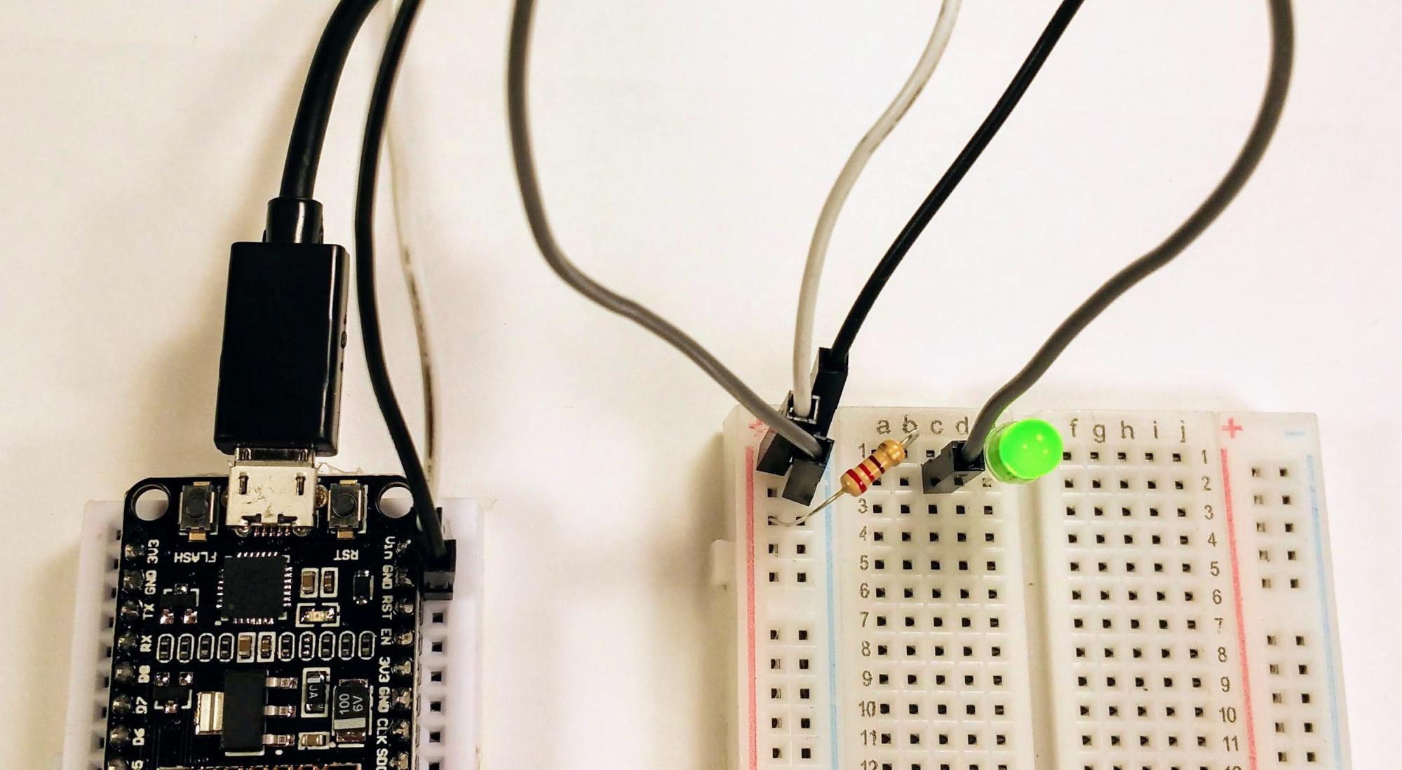
We should be able to trace +5 volts coming in the white wire, going down the red power rail to the resistor, connecting through the resistor to the left row 1 of the breadboard, through this row to the positive pin of the LED. Going through the LED to the negative pin that is connected to the left row 2 of the breadboard, through this row of the breadboard to the grey wire, and then through the grey wire to the blue ground rail, and then through the blue ground rail to the black wire that is connected to ground. This makes a complete circle for the electrons to flow in, and is called a “circuit path.”
We can test that our circuit works by connecting the NodeMCU into power. Plug the micro USB cable into the NodeMCU module and then plug the other end of the USB cable into the battery pack. Once you turn the battery pack on, you should see your LED light up. If it doesn’t, you may have plugged it in backwards. Try flipping it so that the lead that was in row 1 is now in row 2, and visa-versa.
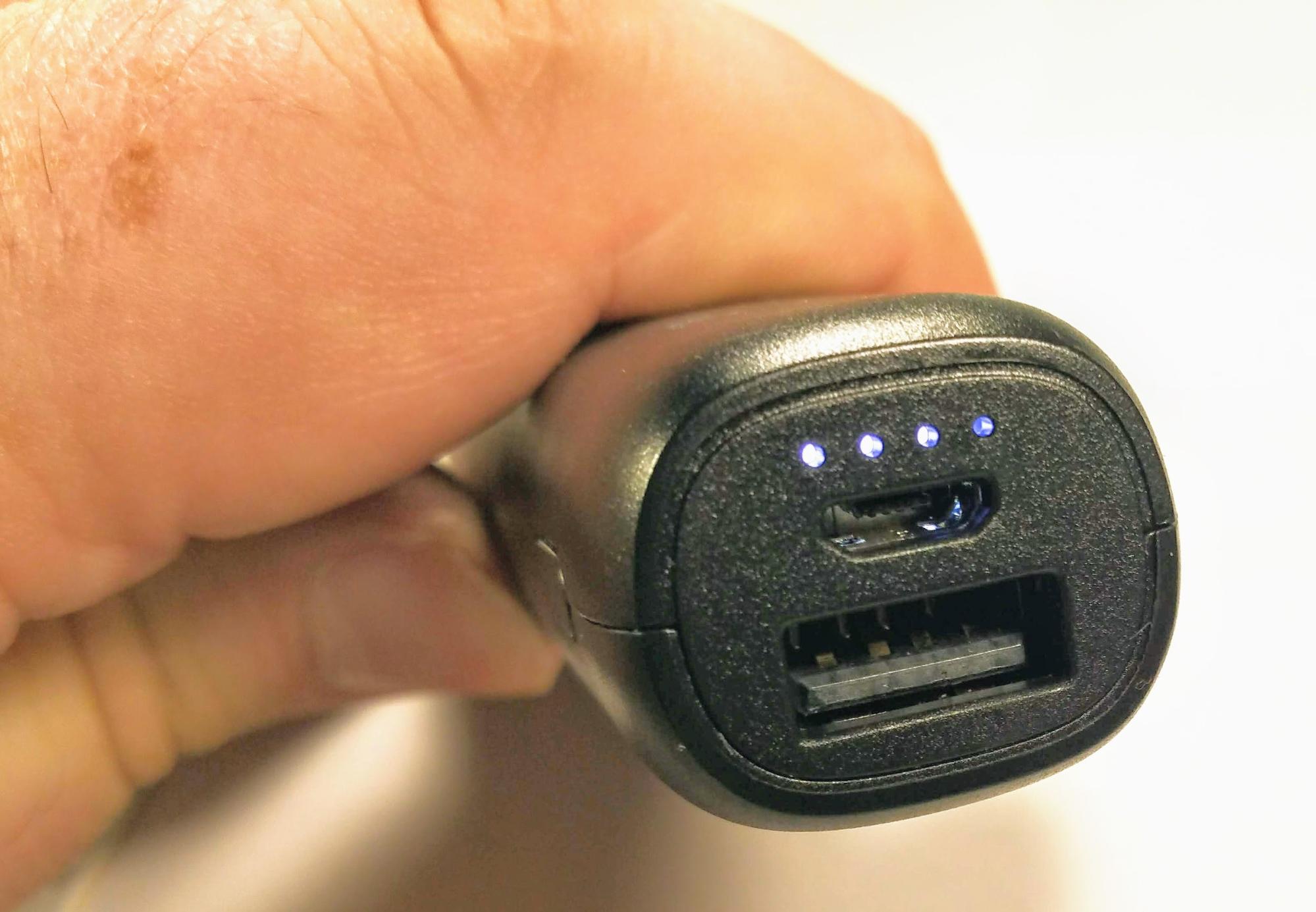
You’ll need to make sure that the battery pack is on. There is a button on the side. When you press it you should see the lights next to the plug light up. These indicate the level of charge of the battery pack. Four lights mean a full charge. For the circuits we are building, we use such little power that often the battery pack thinks nothing is plugged into it, and turns off. When this happens, just push the button on the side, and it will come on again.
Congratulations, you’ve built your first circuit! Yay, reeba, reeba!
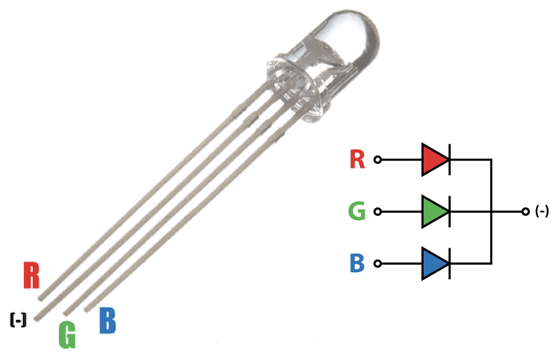
Sometimes more than one LED is placed in the same package. Later we will be using an LED that has three colors: Red, Green and Blue. This allows us to simulate a “pixel” on a screen and show a wide range of colors by adjusting how much red, green or blue. There are two kinds of RGB LEDs: Common cathode (grounds connected together) and common anode (positive sides connected together.)